|
Control
- Open loop vector control
- Speed or torque control
- Speed reference input: 0-10V, 0-20mA, 4-20mA, (-10 to +10V SM-I/O
Lite option)
- 4 digital inputs- World (enable, run forward, run reverse,
local/remote)- USA (not stop, run, jog, local/remote)
- Switching frequency: 3 (default) – 6 – 12– 18 kHz
- Output frequency 0 to 1500Hz
- Accel and Decel ramps (linear and S type)
- Positive logic control
- Serial communication - Modbus RTU RS485 via RJ45 connector- Baud
rate 4800, 9600, 19200or 38400 bits per second
- DC injection braking as standard
- Dynamic braking transistor as standard
- Dynamic motor flux V/Hz for energy saving
- Quadratic motor flux V/Hz for fan and pump optimization
Protection
Under voltage, Supply and DC Link overvoltage, Phase loss, Drive
overload, Instantaneous over current, Short circuit, Ground fault, Drive
thermal, Watchdog, Motor thermal
|
General Characteristics
- Maximum overload 150% of rated current for 60s
- Intelligent Thermal Management (ITM) optimizes switching frequency
- 8 preset speeds
- Flying start
- Mains dip ride through
- Automatic no-spin auto tune for fast performance optimization
- Keypad access to all parameters for more demanding set-ups
Environment
- P20
- NEMA 1 rating with optional cover
- Ambient temperature -10 to +40°C @ 3kHz switching
- Humidity 95% maximum (non-condensing)
- Electromagnetic Immunity complies with EN61800-3 and EN61000-6-3 and
4
- Electromagnetic Emissions complies with EN61800-3 (second
environment) as standard. Complies with EN61000-6-3 (residential) and
EN61000-6-4 (industrial) generic standards with optional footprint EMC
filter
|
|
 |
|
SK
Selection
|
|
| |
Typical Motor
Power
|
100%
continuous
output Current
(A)
|
150% overload
current for 60s
(A)
|
| Order Code |
Size
|
Supply Voltage and
Frequency
|
(kW)
|
(hp)
|
| SKA 1200025 |
A
|
200 to 240 Vac
±10%
1 phase
|
0.25
|
0.3
|
1.7
|
2.55
|
| SKA 1200037 |
0.37
|
0.5
|
2.2
|
3.3
|
| SKA 1200055 |
0.55
|
0.75
|
3.0
|
4.5
|
| SKA 1200075 |
0.75
|
1
|
4.0
|
5.0
|
| SKB D200110 |
B
|
200 to 240 Vac
±10%
1/3 phase
|
1.10
|
1.5
|
5.2
|
7.8
|
| SKB D200150 |
1.50
|
2.0
|
7.0
|
10.5
|
| SKC D200220 |
C
|
2.20
|
3.0
|
9.6
|
14.4
|
| |
Typical Motor
Power
|
100%
continuous
output Current
(A)
|
150% overload
current for 60s
(A)
|
| Order Code |
Size
|
Supply Voltage and
Frequency
|
(kW)
|
(hp)
|
| SKB 3400037 |
B
|
380 to 480 Vac
±10%
3 phase
|
0.37
|
0.5
|
1.3
|
1.95
|
| SKB 3400055 |
0.55
|
0.75
|
1.7
|
2.55
|
| SKB 3400075 |
0.75
|
1
|
2.1
|
3.15
|
| SKB 3400110 |
1.1
|
1.5
|
2.8
|
4.2
|
| SKB 3400150 |
1.5
|
2
|
3.8
|
5.7
|
| SKC 3400220 |
C
|
2.2
|
3
|
5.1
|
7.6
|
| SKC 3400300 |
3.0
|
4
|
7.2
|
10.8
|
| SKC 3400400 |
4.0
|
5
|
9.0
|
13.5
|
|
|
|
 |
|
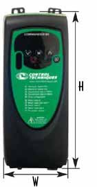
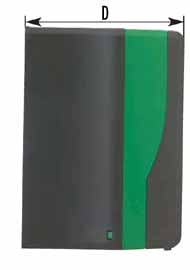
Dimensions
|
Drive
size
|
w
|
h
|
d
|
|
mm
|
in
|
mm
|
in
|
mm
|
in
|
|
A
|
75
|
2.95
|
140
|
5.5
|
145
|
5.71
|
|
B
|
85
|
3.35
|
190
|
7.48
|
156
|
6.14
|
|
C
|
100
|
3.93
|
240
|
9.45
|
173
|
6.81
|
|
|
|
|
 |
|
|
|
|
Cables
The table below is only a guide; refer to local
wiring regulations for correct size of cables. In some cases, a
larger cable size is required to avoid excessive voltage drop.
Use 105°C (221°F) (UL 60/75°C temp rise)
PVC-insulated cable with copper conductors having a suitable
voltage rating, for the following power connectors:
- AC supply to external EMC filter (when used)
- AC supply (or external EMC filter) to drive
- Drive to motor
- Drive to braking resistor Motor cables The recommended output
cable sizes assume that the motor maximum current matches that of
the drive. Where a motor of reduced rating is used, programmed
with the correct motor rated voltage.
Fuses
The AC supply to the drive must be fitted with suitable
protection against overload and short circuits. Tables below show
the recommended fuse ratings. Failure to observe this requirement
will cause risk of fire.
A fuse or other protection device must be included in all live
connectors to the AC supply.
An MCB (miniature circuit breaker) or MCCB (molded case circuit
breaker) with type C tripping characteristics maybe used in place
of fuses as long as the fault clearing capacity is sufficient for
the installation.
Fuse types
Europe: Type G HRC fuses complying with EN60269 parts1 and 2 (BS88)
USA: Bussman Limitron KTK series, class CC fast acting
|
|
| Model |
SKA12
|
SKBD2
|
SKCD2
|
|
00025
|
00037
|
00055
|
00075
|
00110
|
00150
|
00220
|
|
1ph
|
3ph
|
1ph
|
3ph
|
1ph
|
3ph
|
Recommended input
supply fuse (A) |
6
|
10
|
16
|
20
|
16
|
25
|
16
|
32
|
20
|
| Control cable (mm2) |
≥0.5
|
≥0.5
|
| (AWG) |
20
|
20
|
Recommended input
cable (mm2) |
1.0
|
1.5
|
2.5
|
1.5
|
2.5
|
1.5
|
4.0
|
2.5
|
| (AWG) |
16
|
14
|
12
|
14
|
12
|
14
|
10
|
12
|
Recommended motor
cable (mm2) |
1.0
|
1.0
|
1.5
|
| (AWG) |
16
|
16
|
14
|
Recommended brake
resistor cable (mm2) |
1.0
|
1.0
|
1.5
|
| (AWG) |
16
|
16
|
14
|
|
|
| Model |
SKB34
|
SKC34
|
|
00037
|
00055
|
00075
|
00110
|
00150
|
00110
|
00150
|
00400
|
Recommended input
supply fuse (A) |
TBA
|
TBA
|
10
|
16
|
20
|
| Control cable (mm2) |
≥0.5
|
≥0.5
|
| (AWG) |
20
|
20
|
Recommended input
cable (mm2) |
1.0
|
1.5
|
2.5
|
| (AWG) |
16
|
14
|
12
|
Recommended motor
cable (mm2) |
1.0
|
1.0
|
1.5
|
| (AWG) |
16
|
16
|
14
|
Recommended brake
resistor cable (mm2) |
1.5
|
1.5
|
| (AWG) |
14
|
14
|
|
|
|
|
|
 |
|
Standards
The drive conforms to the following standards. |
|
| |
Standard
|
Level/Class
|
| Transport temperature cycle |
IEC68-2-14
|
-40 - +30ºC
5 cycles
|
| Storage humidity |
IEC68-2-56
|
93%, 40ºC
4 days
|
| Storage Condensation |
IEC68-2-30
|
Humidity cycle
|
| Bump (shock) test |
IEC68-2-29
|
18g, 6ms,
100 times/direction
for all 6 directions
|
| Random vibration |
IEC68-2-64 & IEC68-2-36
|
0.01g2/Hz 5-20Hz
-3dB/octave
20-200Hz
30 min per axis, 3 axes
|
| Free fall test, packaged |
IEC68-2-32
|
to
|
| Impact test for operator-accessible parts (impact hammer
test) - could also apply to parts subject to rough treatment
during installation or commissioning, e.g. keypad, terminal
area & cover |
clause 8.2 of EN61010-1
|
0.5j
|
| Robustness of terminals |
EN60947
UL1059
UL486
UL508C
|
|
| Swept sinusoidal vibration test |
IEC68-2-6
|
3.5mm 2 – 9Hz
10m/s2 9 –200Hz
15m/s2 200-500Hz
|
|
|
Note:
environmental tests are derived from ETSI EN 300 019-2-2 1999 for
public transportation |
|
Safety
The drive is designed to meet the following standards.
|
|
| |
Standard
|
Level/Class
|
| Europe: |
|
|
| To comply with Low Voltage Directive 73/23/EEC by creating a
technical File following CT design procedure. |
See note 1
|
-
|
| US: |
|
|
| Basic safety |
UL508C
|
-
|
| Enclosure category NEMA 1 |
See note 2
|
-
|
| International: |
|
|
| Ingress |
IEC60529
|
IP20
|
|
|
NOTE 1 The safety file
procedure applies the EN61800-5-1 (IEC61800-5-1) standard
(Electrical and thermal requirements, electrical adjustable speed
drive systems)
NOTE 2 The drives require an
optional top cover kit to meet the NEMA 1 requirements. Any
operator-accessible parts will conform to EN61010-1 (Safety
requirements for electrical equipment for measurement, control, and
laboratory use). European installers will apply EN60204-1 to their
control panels, so the drive design will be compatible with
EN60204-1 (Safety of machinery - electrical equipment of machines).
|
|
|